Whats GTL
GTL Introduction
 Gas to Liquids (GTL) takes natural gas and converts it to low-sulphur environmentally friendly diesel, naphtha, and LPG. (GTL) technology has been around for decades, however, only with advances in catalyst research has it become economically attractive.
GTL Process Overview
Natural Gas
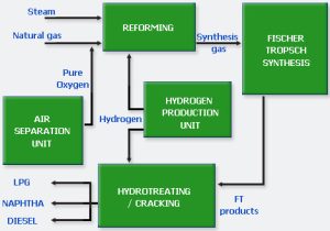
Natural Gas is a main Feedstock procured by ORYX GTL to produce GTL. It is drawn from Qatar’s North Gas field and routed to LNG facilities located in Ras-Laffan Industrial City in the north of Qatar.
 After removing unwanted components from the natural gas it is sent to ORYX GTL as its main feed stream, of which around 96% is used to produce synthesis gas while the rest is used for fuel.
Air Separation Unit
The air separation unit consists of two trains. Each train is one of the biggest of its kind in the world. The main steps of each of the ASU trains are: Compression of atmospheric air Initial cooling,
drying, and CO2 removal Further compression, cooling, and high-pressure and low-pressure separation The “liquid air” is then routed through cryogenic distillation to produce pure oxygen and pure nitrogen Pure Oxygen is sent to the Reforming unit to produce synthesis gas Nitrogen is used in the facility as a utility.
Reforming
The main steps in this unit are: Natural gas is desulphurised and then pre-reformed to produce a feed stream for the Auto-Thermal Reformer. The reforming of methane and steam to Synthesis gas ,with a specific ratio of hydrogen to carbon monoxide, is then completed in the Auto Thermal Reformer.
Produced Synthesis gas is then cooled down by generating HP Saturated steam in a Waste Heat Boiler. The synthesis gas produced is the feed stream to the Fisher Tropsch unit
Fischer Tropsch
The main steps of each of the two Fischer Tropsch trains are:Preheating the synthesis gas from the Reformer
Reaction of the gas by the Fischer Tropsch process over proprietary catalyst in the Sasol Low Temperature Slurry Bed Reactors
The high-yield of long-chain paraffin hydrocarbons from the Sasol catalyst is cooled and separated into tail gas, wax, hydrocarbon condensate, and reaction water
The tail gas is sent for further hydrocarbon recovery
The hydrocarbon condensate and wax are sent to the hydrocracker
The water is treated and exported as irrigation water
Hydrotreating / Cracking
The proprietary catalyst used to hydro-treat and crack the Fischer Tropsch products is supplied by Chevron.A minimal amount of olefins is hydro-treated in the reactor while longer chain paraffins are broken down into shorter chains
The resulting two phase reactor product is then routed to a series of flash vessels to separate the liquid from the vapor. The Vapor is recycled and the liquid is then fractionated and treated into the plant’s final products.
Hydrogen Production Unit
The main steps in this unit are:Natural Gas de-sulfurisation.
Steam reforming – reaction of steam with a hydrocarbon over a catalyst at around 750-800oC to form hydrogen and carbon oxides
Shift conversion – carbon monoxide reacts with steam to produce carbon dioxide and additional hydrogen.
Product purification – Pressure Swing Absorption unit (PSA) is used to produce 99.99% product hydrogen and an-off gas used in the fuel system.
H2 is sent to the Reforming and Hydro Treating/Cracking unit
